
Description
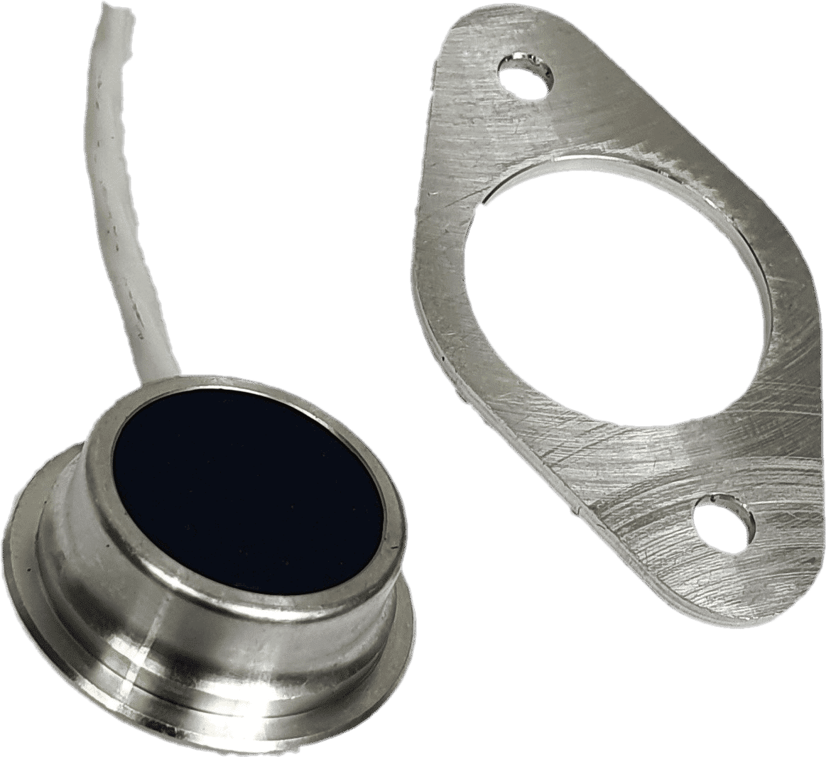
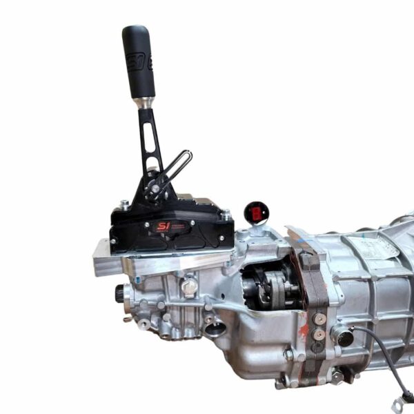
0-5V Hall Effect Gear Position Sensor
This high-accuracy sensor is designed specifically to interface with the internal magnets factory-fitted inside all S1 Sequential shifters. Utilizing modern Hall Effect technology, it provides a precise 0–5V analogue output to communicate gear position to your digital dash, ECU, or gear indicator.
Technical Specifications & Wiring
The sensor requires a stable 5V DC supply. Please follow the wiring guide below carefully, as incorrect wiring or over-voltage will cause permanent damage to the sensor.
-
White/Yellow or Orange: 5V Supply In
-
White/White: Signal Out (0–5V)
-
White/Blue or Green: Ground (GND)
⚠️ Critical Safety Note: Never exceed 5.5V. Wiring the sensor incorrectly or supplying excessive voltage will immediately destroy the internal circuitry.
Integration & Setup Tips
-
Dash & ECU Logging: If you are using this sensor to display gear position on a digital dash or for ECU logging (such as gear-based boost control), you must also wire in your gearbox’s Reverse Switch. Because 1st gear and Reverse occupy the same physical position on the sensor’s sweep, the software requires the reverse switch signal to differentiate between the two.
-
Testing Procedure: You cannot test this sensor by checking resistance with a multimeter. To verify functionality, you must provide a 5V power source and measure the Voltage output on the signal wire as you shift through the gears.
Thermal Management
This sensor has a maximum operating temperature of 120°C (248°F), which is the standard limit for high-performance Hall Effect sensors.
-
Signal Dropout: If you experience signal “dropouts” during intensive track sessions, it is likely that your transmission tunnel or gearbox casing temperatures are exceeding the 120°C limit.
-
Solution: We recommend ensuring adequate transmission cooling or adding thermal shielding. Maintaining reasonable gearbox temperatures not only protects the sensor but also significantly extends the life of your gear set and synchros.
⚠️ Compatibility Warning (Pre-July 2022)
Please check your equipment date before ordering. These current-generation sensors utilize the full voltage range (0V to supply voltage).
-
NOT compatible with S1 Sequential gear indicators sold before July 2022.
-
Older indicators were designed for a “clipped” signal sensor (which limited output by 0.5V at each end) that is no longer available due to global component shortages.
-
If you are replacing a sensor for an older system, you will likely need to upgrade both the sensor and the indicator to the current standard.

Craig Meyer (verified owner) –
Charles Haynsworth (verified owner) –
Kenneth B. (verified owner) –
Looks fantastic, let’s hope it’ll do better than the previous one…
Steven Conder (verified owner) –
Keith Collins (verified owner) –
Anonymous (verified owner) –
Damon Miller (verified owner) –
Tony Baya (verified owner) –
Saeed Saif Mohammed Hyat (verified owner) –
Patrick Laughlin (verified owner) –
Mohannad Almuagle (verified owner) –
Coffs Mechanical (verified owner) –
Greg (verified owner) –
Stephan B. (verified owner) –
Installation instructions With the wiring diagram
RH Bullard (verified owner) –
John Yde (verified owner) –
Brandon Hitchins (verified owner) –